Fall semester 2021-2025: Teaching for a project-based practicum and presentations from third semester students of materials science about the creation and study of a special type of electric motor
Last update 10 January 2025
Since 2021 the practicum for third semester students of materials science is performed in a new way. There are several project topics which have in common the creation and manufacturing of a device and optimizing and / or studying its properties. The project topic or device should be something which allows many potential types of design and / or control and a creative manufacturing, optimizing, and investigation of one or a few specific variant(s) within the available period, namely one and a half days per week within the semester. The concrete work is performed in the so-called Materials Design Lab which was established and is maintained by Thomas Schweizer and Martin Willeke . Thomas Schweizer and several lab assistants supervise the students when they are working in the Materials Design Lab and Martin Willeke organizes the overall practicum schedule.
So far several project topics were offered and implemented, namely the construction of a
- simple ultraviolet spectrometer
- setup for heat conductivity measurements
- Stirling engine
- special electric motor related to the so-called Keppe Motor
Often several student groups did work simultaneously and independently on the same project topic. Each group comprised around five students. The practicum starts with an introductory event around mid September and ends around mid December with a presentation event where each group of students presents their project and results.
The so-called Keppe Motor as project topic was proposed by Frank Lichtenberg and he supervised the students as tutor / advisor and prepared a draft for this webpage. The Keppe Motor is a special type of a brushless electric motor which is integrated in some commercially available fans. The Keppe Motor website external page https://www.keppemotor.com provides various kinds of information and products including a Keppe Motor kit.
The following picture shows a sketch of principle of the Keppe Motor.
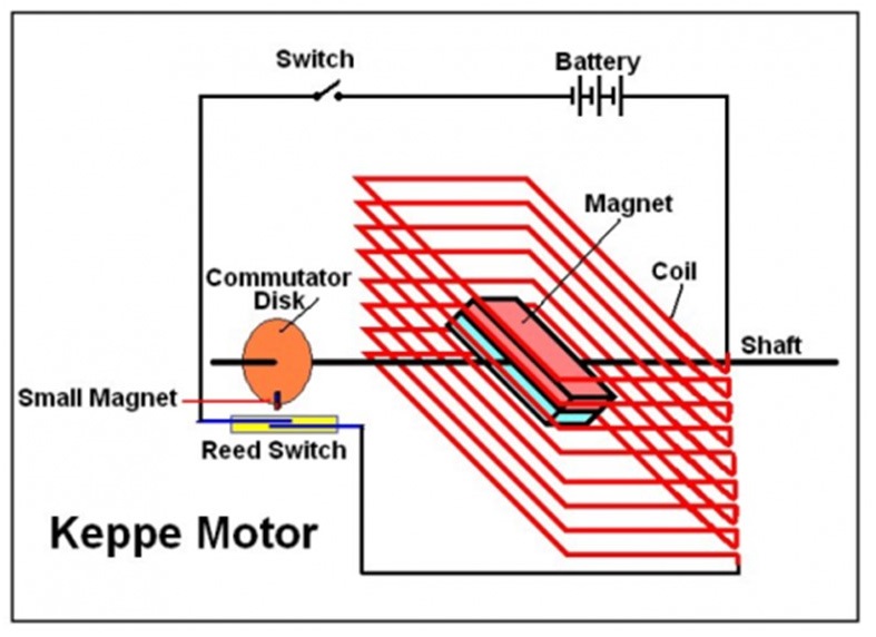
The Keppe Motor concept comprises a turnable permanent magnet which is surrounded by a coil. When an electrical current is flowing through the coil, then a torque is generated which leads to a rotation of the permanent magnet and the shaft. The torque T can be (approximately) described by
T = |B| |H| sin(φ)
whereby B is the so-called magnetic flux density generated by the coil when an electrical current is flowing through it, H is the so-called magnetic field strength generated by the permanent magnet, and φ is the angle between B and H. The torque has the same algebraic sign during the first half of one rotation and the opposite sign during the second half of one rotation. The easiest way to ensure a continuous rotating motion is to interrupt the current through the coil within an angular interval of the second half of one rotation, e.g. around that angular position where the torque with an opposite sign would reach its maximum, i.e. around φ = 270 degrees when the range from φ = 0 to φ = 180 degrees represents the first half of one rotation. Also a flywheel can be used to ensure a continuous rotating motion. The simplest (but not the best) way to interrupt the current is via a reed switch and a small permanent magnet which is attached on the shaft.
The following Portuguese-language video displays the creation of a simple Keppe Motor model in a descriptive and comprehensible way so that it is not necessary to understand the language: external page https://www.youtube.com/watch?v=eZdtuZReufY. Thomas Schweizer discovered this video on the internet.
The Keppe Motor concept offers many mechanical types of design (size, dimensions, materials, weight), plenty electrotechnical variants to control it, and various ways to explore its properties. It can also be used and explored as AC and DC generator (the DC version requires an appropriate circuit).
Thomas Schweizer has created several Keppe Motor models and two of them are shown in the following two pictures. He has also designed, implemented, and explored various kinds of electrical circuits which control the Keppe Motor.
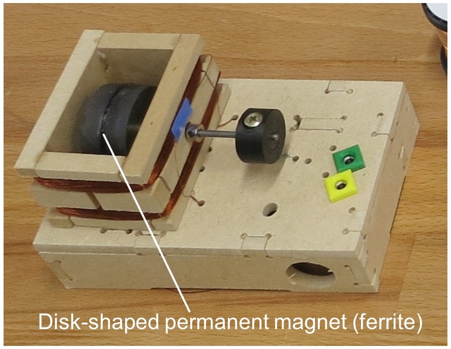
Assembled Keppe Motor kit which was purchased from external page https://www.keppemotor.com and assembled by Thomas Schweizer. The reed switch is not visible in this picture. The picture was taken on 7 September 2021 in the Materials Design Lab.
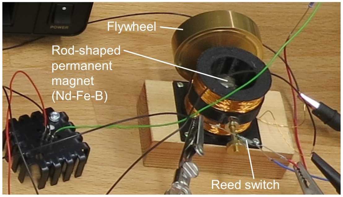
A Keppe Motor model designed and manufactured by Thomas Schweizer. The reed switch engages a circuit which comprises a transistor that switches the current through the coil. Later another kind of regulation and circuit resulted in an increased efficiency and the flywheel was no longer necessary. Picture taken on 7 Sept 2021 in the Materials Design Lab.
It is also allowed to implement mechanical constructions and / or control variants which deviate significantly from the original Keppe Motor concept. The following two pictures show an example, namely a model of a synchronous motor which is not controlled by the angular position of the rotational axis but by a sequential activation of two opposite coils in an angular array of coils.
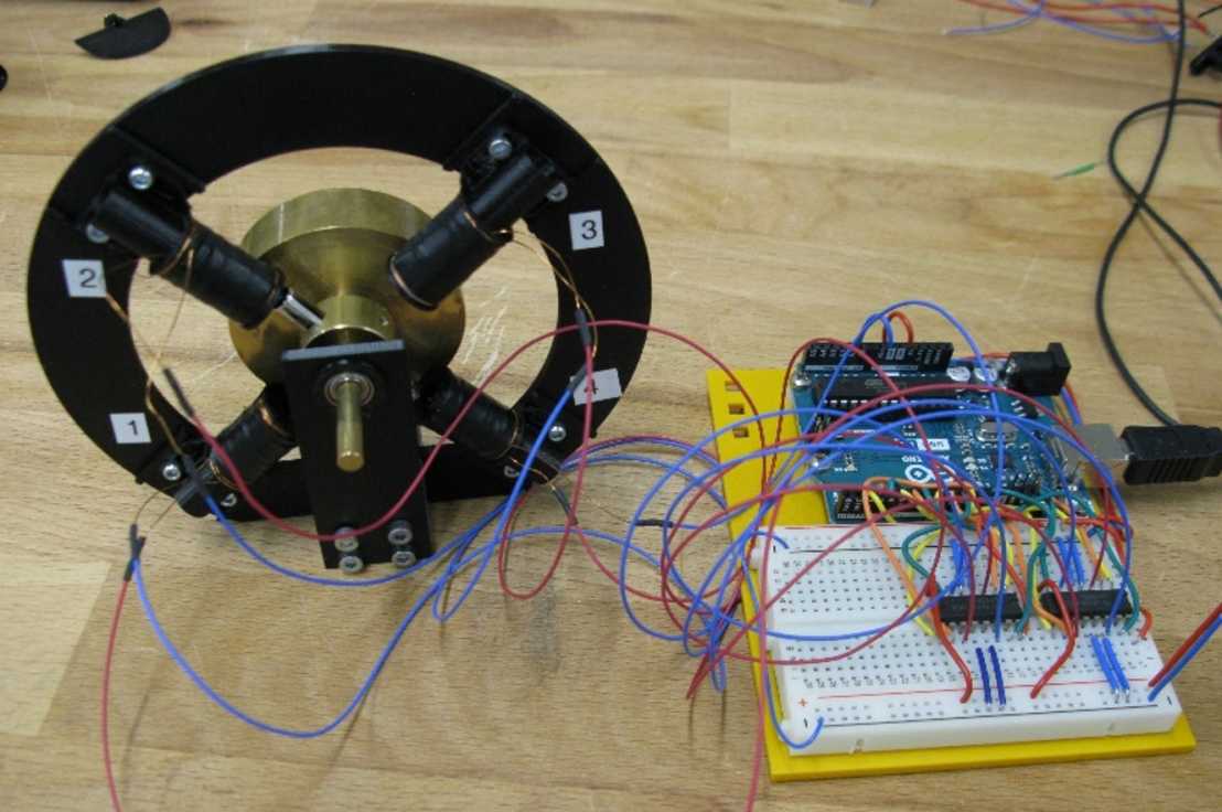
A synchronous motor model and associated control electronics designed and manufactured by Thomas Schweizer. This model with 4 coils requires a manual start and a flywheel to ensure a continuous motion. A larger number of coils would allow an automatic start and a continuous motion without using a flywheel. The implementation of a corresponding model represents a potential student project.
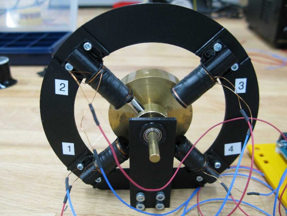
Another picture from the synchronous motor model.
The aims and hints of / for the electric motor project are presented via the following accordion menu.
- Building a working electric motor model
- Experiencing the process from thoughts / ideas / drawings to the implementation and manufacturing of the electric motor model including its potential ups and downs
- Document various features in form of text / pictures / drawings / short videos such as
- the design of the electric motor
- the design and dimensions of some components like the magnet holder, the coil body, the coil, the number of its windings and the diameter of the used (copper) wire
- the materials of which are some components made of
- a sketch of the used circuit diagram to control the electric motor
- the running electric motor
- Determine the approximate energy efficiency of the electric motor, e.g. by lifting a weight and estimating the approximate electric power which was required for it. If desired also other properties of the electric motor can be studied
- Creation of a presentation about the project and its results
- Performance of a practice talk about the project by using the created presentation. Afterwards the students and the tutor view / discuss each slide and implement - if necessary - corrections / improvements / supplements
- Talk about the project at the presentation event by using the created presentation
- It is intended to publish the created presentation via this webpage (the already existing and published presentations are available at the bottom of this webpage)
- The magnet holder and the rotational axis should be made of a non-ferromagnetic material. The ball bearings which are available in the practicum lab contain ferromagnetic materials but this can be considered as tolerable. There are also commercially available ball bearings which do not comprise ferromagnetic materials and they contain balls which are made of a ceramic material. If desired one can additionally construct a magnet holder and / or rotational axis which are / is made of a ferromagnetic material and explore if / how the electric motor works with them / it.
- Estimation of the electric input power of the running electric motor: At the power supply the displayed current fluctuates because during each revolution the coil current is switched on off / reverses its polarity. Also the curves coil current I(t) and coil voltage U(t) do not display an ideal rectangular shape because of the inductance of the coil. Therefore with the available devices in the practicum lab the electric input power cannot be determined precisely and an approximative approach has to be used. Please note also that most power meters can measure the power correctly only for direct current (DC) or sinus-shaped alternating current (AC)
- Measure the magnetic field generated by the permanent magnet nearby its surface and further afar from it
- Measure the magnetic field generated by the current-carrying coil for at least 2 or 3 different currents
- Measure the magnetic field which is generated by a ferromagnetic and magnetically soft material which is inserted into the coil - if such a setup is part of your intended construction
- Explore the appearance of the curves coil current I(t) and coil voltage U(t) during a period which comprises the switching on off / polarity reversal. These curves can be measured with an oscilloscope and reveal how strongly the curves deviate from an ideal rectangular shape
- Use Libre Office Impress or Microsoft Office Power Point for the creation of the presentation. Libre Office is free and can be downloaded from the internet. A published Libre Office presentation can also be viewed by readers who do not have Microsoft Office on their computer
- Start with a title page and specify there the title, authors, date / year of the corresponding fall or spring semester, ETH Zurich with department and project name specification
- The specified authors should not only comprise the students but also other people who have contributed to the project like the lab assistant(s), the tutor of the project, the supervisor of the practicum lab and workshop, and the organizer of the practicum
- After the title page a slide with a content overview is recommended
- Implement page numbering
- The presentation should describe the project and its results in an understandable way so that others can more or less comprehend it and are able to build a replica of the electric motor
- The recommended number of slides is around 20 or 25
- Use font sizes which can be easily read, for example at least 16 or 18 for Arial - exceptions are allowed, for example when it is intended to document several detailed information on one slide
- The presentation should also comprise 1 or 2 slides which describe the contributions of the authors who are specified on the title page
- End the presentation with a slide "Thank you for your attention" or something similar
- If desired additional slides with very specific information can be added after the "Thank you for your attention" slide and that content is usually called Appendix
Before providing the presentations from the students who have performed the Keppe Motor project it appears appropriate to call attention to safety instructions for working with strong permanent magnets of the type Nd2Fe14B:
Download Download safety instructions in English as pdf (PDF, 57 KB)
Download Download safety instructions in German as pdf (PDF, 58 KB)
Download Download short mp4 type safety video about strong permanent magnets and glass (MP4, 1.8 MB)
Presentations from the students who have performed the Keppe Motor project:
Fall semester 2021: ppsx type PowerPoint show (in German) with 4 embedded short videos from Leonardo Bolliger, Marco Ferretti, Alessandro Bellucci, Vita Augusta Onorina Bianca Rossi, Andrea Mäusli, Camillo Sirvinski, and Maxim Vovk. Title: “Projekt: Keppe Motor“. Date of publication: 19 January 2022.
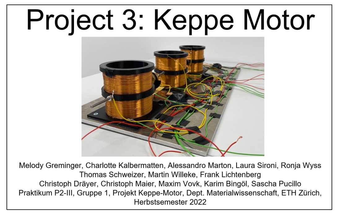
Fall semester 2022: ppsx type PowerPoint show with 2 embedded short videos by Melody Greminger, Charlotte Kalbermatten, Alessandro Marton, Laura Sironi, Ronja Wyss, Thomas Schweizer, Martin Willeke, Frank Lichtenberg, Christoph Dräyer, Christoph Maier, Maxim Vovk, Karim Bingöl, and Sascha Pucillo. The author list comprises all members of Group 1 as well as others who contributed to this project, see author contributions on pages 23 and 24 in the presentation. Title of the presentation: "Project 3: Keppe Motor". Date of publication: 27 March 2023.
Download Download this presentation as ppsx type PowerPoint show with 2 embedded short videos (PPSX, 18 MB)
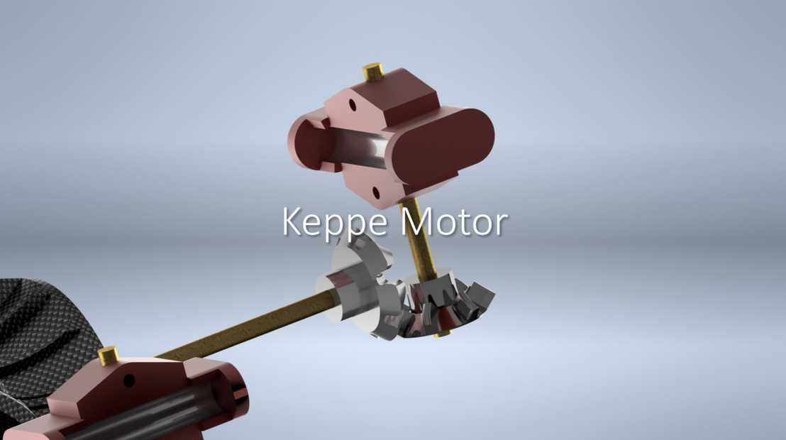
Fall semester 2022: pdf presentation (in German) from Jona Ammann, Leonardo Del Gaudio, Oliver Heck, Florent Liechti, and Aaron Locher from Group 2. Title: "Keppe Motor". Date of publication: 3 March 2023.
Comments on the presentation of Group 2 from fall semester 2022: At the second last working day the electric motor of Group 2 did not yet work but there was still hope to put it into operation on the last available working day. Therefore it was decided to perform no practice talk for the presentation event which took place on 20 December 2022. Instead the last possible working day was used for further attempts to put the motor into operation. However, it did not work and the main reason for that was a too large friction of the relatively complex cogwheel system which was part of their design. This outcome should not be considered as a failure but simply as a result without any judgement. If a planned project objective cannot be achieved, then this is important learning experience, especially in the field of research and development and when only a limited period of time is available.
Fall semester 2023: ppsx type PowerPoint show (in German) with 5 embedded videos from Livienne Häusler, Khye-Wen Ho, Dominik Kasper, Luc Heiniger, Leon Brunella, Thomas Schweizer, Martin Willeke, Frank Lichtenberg, and Florent Liechti. Title: “Keppe Motor“. Date of publication: 9 January 2024.
Fall semester 2023: ppsx type PowerPoint show (in German) with 5 embedded videos from Jonathan Amara, Lars Bangerter, Ivo Gmür, David Lindenmann, Samuel Ziegler, Thomas Schweizer, Martin Willeke, Frank Lichtenberg, Cedric Steiner, and Leonardo Del Gaudio. Title: “Keppe Motor“. Date of publication: 11 January 2024.
Download Download this presentation as ppsx type PowerPoint show with 5 embedded videos. (PPSX, 59.4 MB)
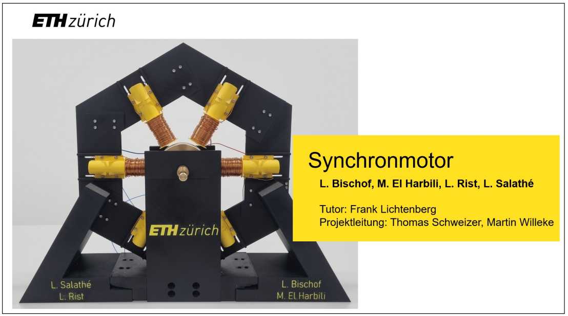
Fall semester 2024: ppsx type PowerPoint show (in German) with 1 embedded animation by L. Bischof, M. El Harbili, L. Rist, and L. Salathé. Tutor: Frank Lichtenberg. Project management: Thomas Schweizer and Martin Willeke. Title of the presentation: "Projekt P2-III / Keppe Motor" (page 1 of the presentation) and "Synchronmotor" (displayed page 2 of the presentation). Date of publication: 10 January 2025.
Download Download this presentation as ppsx type PowerPoint show with 1 embedded animation (PPSX, 10.8 MB)
Within the available time of the project period it was not possible to put the constructed model of a synchronous motor into a reliable operation. Only sometimes it did run with a low speed of rotation and then it came to a standstill after a while. The motor may later be used by other students to implement and study some modifications which are suggested (in German) on page 18 of the presentation. Also another way to control the motor can be constructed and studied, namely by switching the coils via the angular position of the rotational axis - even if this approach is unusual for a model of a so-called synchronous motor.
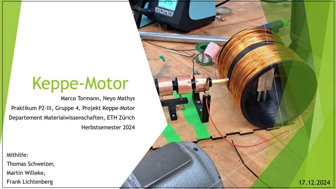
Fall semester 2024: ppsx type PowerPoint show (in German) with 2 embedded videos by Marco Tormann and Neyo Mathys. With support by Thomas Schweizer, Martin Willeke, and Frank Lichtenberg. Title of the presentation: "Keppe-Motor". Date of publication: 10 January 2025.
Download Download this presentation as ppsx type PowerPoint show with 2 embedded videos (PPSX, 34.6 MB)